Boundary Conditions
After defining our flow analysis Model, we assign conditions at our inlet and outlets using Boundary Conditions. The Flow Analysis block auto-generates an empty Boundary Condition List.
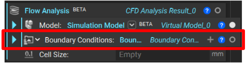
Assign Boundary Conditions

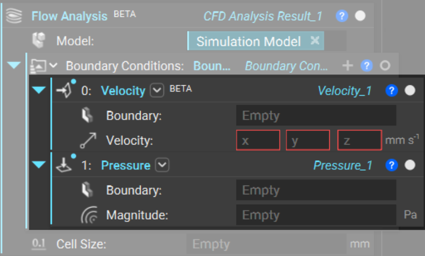
Within the Boundary Condition List, we describe the fluid’s velocity.
Velocity is a Boundary Condition we typically assign at the inlet(s) of the fluid domain.
Pressure is a Boundary Condition we typically assign at the outlet(s). A good practice is to assign a gauge pressure of 0 to determine pressure differential across your system.
Define a Boundary for Each Boundary Condition
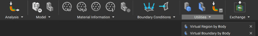
Now, we must define a location at which to apply these boundary conditions. We do these with virtual boundaries.
Just as we saw with the FE Domain versus the Virtual Domain in the Simulation Model, the flow analysis uses virtual boundaries rather than finite element (FE) boundaries. We create these using the Virtual Boundary by Body block.

As a rule of thumb, we should define the boundary thickness as less than 0.5*(cell size).
Note: The boundary of a fluid domain with which is not used to define an pressure/velocity boundary conditions is considered to have a no slip boundary condition. At these boundaries, the fluid velocity is 0.