Review: FE Connectors
You will need connectors if working with multiple domains in your Parametric FE Model. Review these connectors from 240: Intro to Simulation below.
Tie Constraint
A Tie Constraint is a rigid connection that ties two nodes together. Tie constraints make the displacement of the selected nodes equivalent, effectively removing one degree of freedom from the system.
Choose the Independent nodes and the Dependent nodes using a boundary selection block. The Independent boundary looks for the Dependent boundary within a specified tolerance. An error will occur if the tolerance is too low to locate the boundary. You can fix this error by increasing the tolerance or modifying the boundary. The Rotation checkbox toggles the option to tie rotational degrees of freedom. You can see an example of this below.
Structural Bonded Contact
A Structural Bonded Contact is an elastic connection between the two models that allows relative motion with a defined stiffness. Designers typically use these to model two surfaces glued together by some material with a vastly different stiffness than the connected surfaces, allowing the bonded surfaces to not move entirely in sync but have specific resistance between them. It’s often used to calculate contact failure and to model connected/welded surfaces more accurately, but generally for any connection dictated by a finite stiffness.
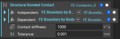
Note that the setup of the Structural Bonded Contact is very similar to the setup of a Tie Constraint, but now we define the Contact Stiffness.
Tip:
We recommend a Contact Stiffness of 0.5 * (Young’s Modulus of Part 1 + Young’s Modulus of Part 2). Another method of determining the contact stiffness is k = E * A/d (where A is the contact area and d is the contact layer thickness).
You can also use Cyclic Symmetry (Beta) and Rigid Connectors (Beta) in your model.