Constraints
The Constraints input in the Field Optimization block is optional as the block inputs (Max Iterations, Min Objective Change, Min Variable Change, and Move Limit) and the Parametric FE Domains used in the model constrain the problem. However, most field optimization problems contain additional constraints.
You can use all the design responses available for topology optimization in Field Optimization. Field optimization supports all geometric constraints but the Extrusion Constraint and the Overhang Constraint.
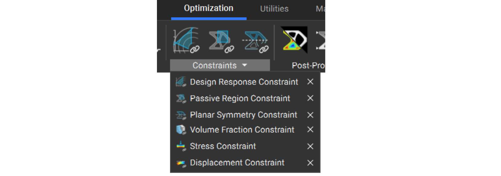
A defined design response drives the field optimization result. The most commonly used constraint applies a minimum or maximum bound to a design response, such as volume fraction, displacement, or stress.
Choose a design response to constrain the problem, ensuring the solution meets and falls under or exceeds your quantitative restriction (dependent on your choice), for example:
Tips:
The Passive Regions Constraint specifies a volume in which the field optimization process will not modify the topology.
Specify any FE region. By default, the FE regions for the boundary conditions are passive regions.
You can add this to the constraints list to ensure symmetry in the resulting part. We recommend using a symmetrical FE Mesh that matches the planar symmetry of the field optimization constraint, using the Mirror FE Mesh block. Although this constraint yields a symmetric geometric result, it does not require symmetric boundary conditions.
The model should be inherently symmetric for this to work. Planes should be orthogonal to the model and placed through the centroid of the FE model.
To create a symmetric mesh: