Thermal Connectors
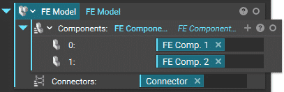
Thermal connectors are typically used to enable heat flux between separate meshes in a model by thermally linking them. These are analogous to structural bonded contacts and tie constraints commonly used in structural stress analyses. Thermal connectors are necessary if there are multiple Components in the FE Model.
In heat sink applications, a thermal paste or an interface material fills microscopic imperfections and maximizes heat transfer between the mating surfaces of the heat source and heat sink. Thermal connectors conveniently model such interfaces.
Thermal Bonded Contact
Thermal connectors are modeled with a Thermal Bonded Contact block which enables heat flux between two components. As in other FEA tools, the thermal bonded contact is based on a master-slave formulation.
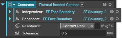
The Thermal Bonded Contact block inputs are:
- Independent: Independent (master) mesh, with entities as Faces only
- Dependent: Dependent (slave) mesh
- Resistance: Resistance of the thermal bonded contact
- Tolerance: A suitable tolerance for the distance between the independent mesh and the dependent mesh to create the thermal bonded contact
- Note: Independent and Dependent meshes can be selected via:
- FE Boundary by Flood Fill
- FE Boundary by Body
- FE Face Boundary
- Boundary by Body
To learn more about meshing and selecting regions of a mesh, please refer to the 102: Guide to Meshing course.
Tip:
Experimenting with different Tolerance values may help achieve optimal definition of the thermal bonded contact between two FE Meshes.
Generally, the dependent (slave) mesh should have a more refined mesh.
Resistance
Resistance (K/W) input in the Thermal Bonded Contact block is the reciprocal of thermal contact conductance (W/K), typically measured in experimental tests.