Method 3: Homogenization
This method uses homogenized material representation to define and simulate lattice structures. It is a two-step simulation process that breaks the problem down into micro and macro scales. This process evaluates a single unit cell of the lattice to generate its effective material properties, which are then used to simulate the bulk lattice volume.
Advantages:
- Faster computation
- Simulates bulk large-scale behavior for large and high-density lattices
- Works for any type of periodic lattice
Limitations:
- Works best with a large amount of unit cells
- Does not consider mechanical behavior such as edge effect and stress concentration in the lattice
- Lattices that must be entirely uniform and periodic, with alignment of the unit cell at boundaries with adjacent unit cells
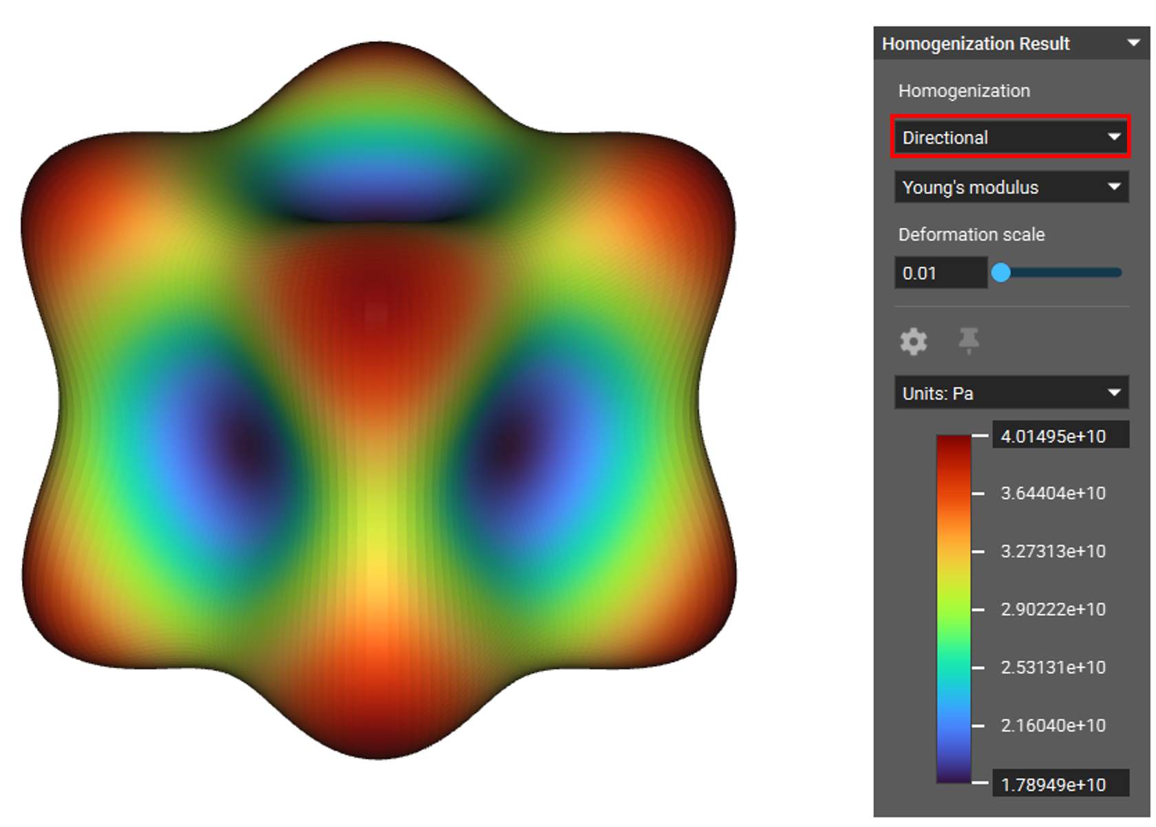
Homogenization takes a single unit cell and characterizes how it would behave in isolation. The result of the homogenization of a unit cell is its stiffness matrix, visualized as colorful blobs in the image below. You can read more about the block and the process here.
This information is used as the material properties for simulating the bulk representative volume where the lattice is located, which simplifies the problem from a large number of unit cells to just one anisotropic or orthotropic material.
| Gyroid | Lidinoid | Neovius |
 |
 |
 |
| Diamond | SplitP | Schwarz |
 |
 |
 |
This method is an approximation, which makes it great for quickly predicting how and to which extent changes in the unit cell will impact the overall design. It is especially good for comparing different lattice types to help make design decisions by narrowing the number of geometry options to a few good candidates. It can also be a powerful tool to help understand the effects of modulating certain characteristics of an architected material.
Homogenized simulation of lattices is, therefore, a great method for evaluating and comparing initial designs. However, it should not be utilized as a final design accuracy method.
Setup
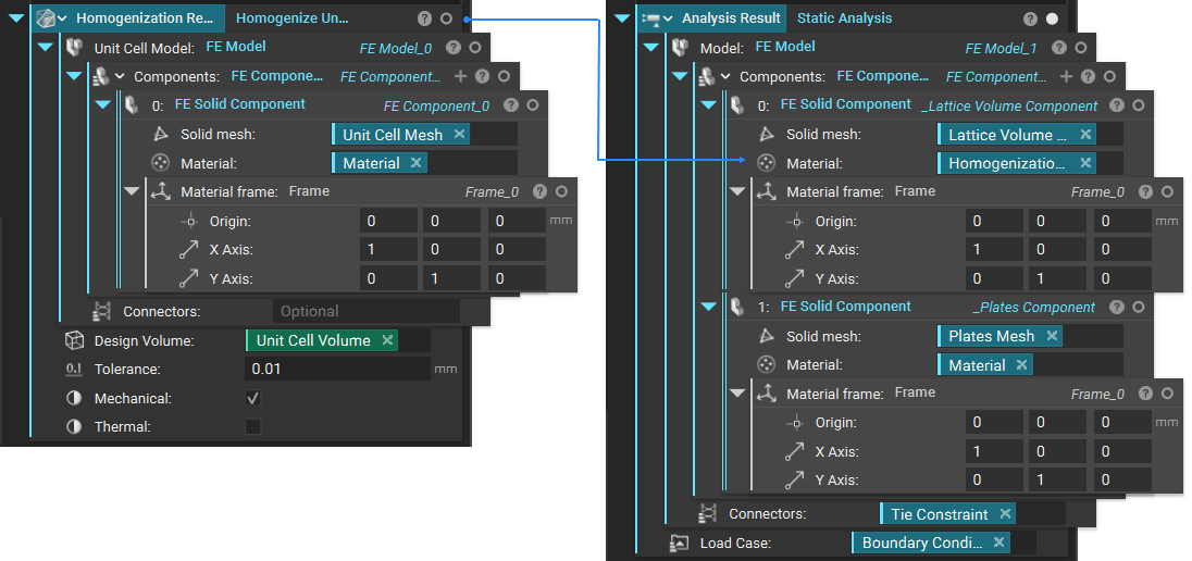
A homogenized simulation requires a two-stage set up. The first stage is running a Solid FEA simulation on a single unit cell of the lattice using the Homogenize Unit Cell block. Creating the FE Model and FE Components is the same as running normal static analysis but without the need to define boundary conditions.
Then, using the results from the first simulation as the material property, run a second Solid FEA simulation on the bulk lattice structure volume. You must create a new FE Model in new FE Components to do this. The homogenization result is the FE Solid Component’s material input representing the lattice volume. This is where you define the boundary conditions.
Stage 1: Homogenizing a Unit Cell
Start by creating your unit cell volume Box and unit cell based on the cell size, type, orientation, and thickness of your lattice structure.
Trim the unit cell to fit the box volume using Boolean Intersect with the volume.
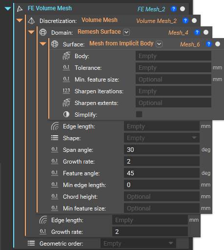
Create the FE Volume Mesh of your unit cell, which you need as input for the FE Component. Below is the recommended workflow. This combination of blocks converts your implicit body into a surface mesh, remeshes it to be suitable for FEA, then generates and discretizes a volumetric mesh with assigned nodes.
Depending on the type of Unit Cell you are using, you may have disconnected floating bits. Remove these after the first meshing step with Mesh from Implicit Body block by putting the mesh into the Split Mesh block. You can either go into the properties of the Split Mesh block and drag out the correct ‘Mesh list’ to use in the next meshing step or use a Filter Mesh List block with a volume threshold.
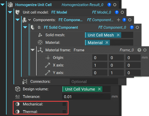
The Homogenize Unit Cell block also includes mechanical and thermal homogenization capability. The block can calculate a unit cell’s elastic properties and equivalent thermal properties, such as conductivity and specific heat. A set of boolean inputs named ‘Mechanical’ and ‘Thermal’ enables users to choose the desired homogenization type. Not selecting both inputs will cause the block to calculate only the density of the unit cell.
After the result is computed, you can visualize the unit cell stiffness matrix by isolating the Homogenize Unit Cell block and changing the setting in the heads-up display to ‘Directional’
You can read the resulting matrix coefficients for compliance and stiffness in the block’s properties tab under material → linear elastic property. Under each coefficient chip, you will find its constant value.
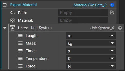
You can export this result in various formats that can be opened in external software such as Ansys or Abaqus using the Export Material block. You can also do this by right-clicking on the Homogenize Unit Cell block and choosing ‘Export’. This option exports file formats .txt or .csv. The exported result is a 6×6 elasticity matrix.
Stage 2: Analysis of Bulk Representative Volume Using Homogenization Results
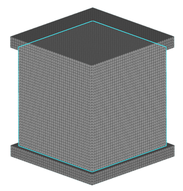
Using the homogenization result as the material for the FE Solid Component that contains an FE Volume Mesh of the bulk lattice region, create a new FE Model that joins that solid bulk component with the FE Solid Component of the surrounding walls via a tie constraint. Also, define your load case in the boundary conditions for the Static Analysis block.
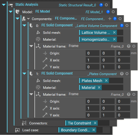
Follow the same recommended meshing workflow to create an FE Volume Mesh for both of these solid components. Make sure that the mesh of the bulk lattice volume is somewhat uniform.
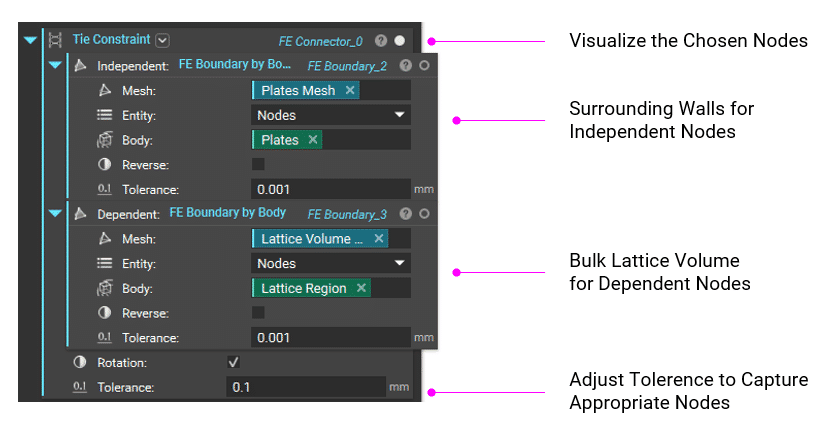
Use the Tie Constraint block to join the independent and dependent nodes of the two solid components. Then, use the FE Boundary by Body block to define the FE boundary.