Method 2: Using Beam or Shell Elements
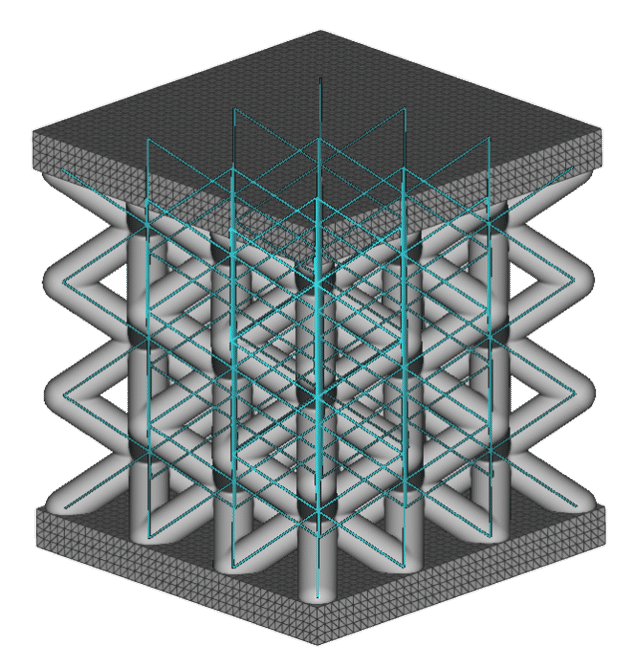
This method treats your lattice structure as beam elements or shell elements. Finite element nodes, connected by lattice beams or shells, are assigned along lattice vertices.
Advantages:
- Fastest computation due to usage of beam elements
- Greatly reduced number of elements
- Works for field-driven or variable beam thickness
Limitations:
- Only works for beam-based or shell lattices
- Ignores blend lattice-wall radius
- Does not consider mechanical behavior such as edge effect and stress concentration in the lattice
Setup
The setup for this method is mostly the same as for running static structural analysis on non-latticed parts. The only difference is that the lattice meshes as beam elements instead of as solid volumetric elements.
As with any static analysis, you create an FE Model containing your component(s) and define your load case in the Boundary Conditions. You can then put the completed FE Model and Boundary Conditions into the Static Analysis block and let it run.
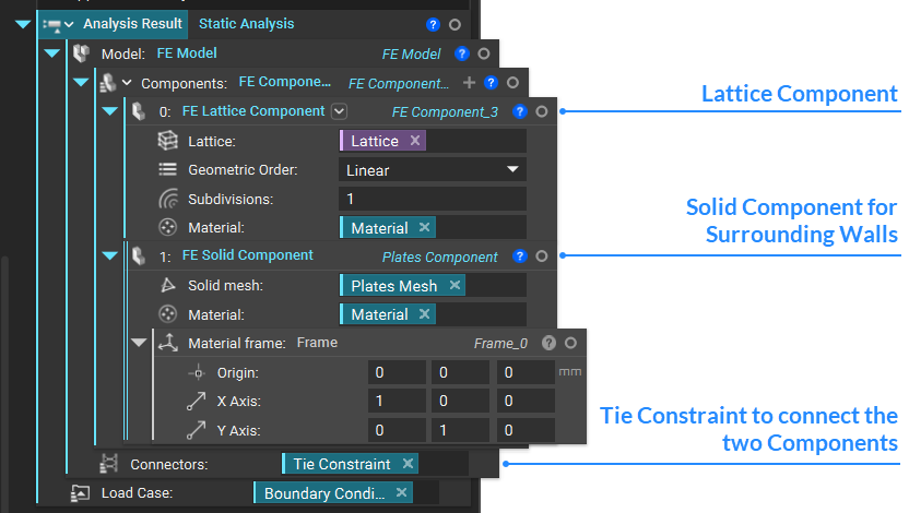
FE Beam/Shell Component
You can use either the FE Component block and fill out the Attribute as FE Beam Attribute or the built-in toolkit block called FE Lattice Component, which lets you skip the step of defining the attribute type.
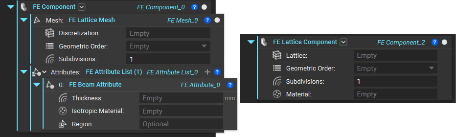
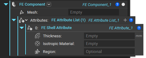
Use FE Shell Attribute in the FE Component block instead to create shell elements.
Since we use the Lattice directly, the lattice component will use the Thickness input from the Lattice blocks.
FE Lattice Mesh
Use the FE Lattice Mesh block to mesh your beam-based or shell lattice. It will take your lattice and assign finite element nodes along lattice vertices connected by beams.
Make sure to correctly isolate and trim your lattice beforehand so that the lattice elements do not extend beyond the volume of the lattice structure or into the surrounding walls.
Note: If you get a warning about short lattice beams, use Collapse Lattice Vertices with a threshold much lower than the unit cell size.
The FE Lattice Mesh block places nodes at the endpoints of each beam, with node(s) along the subdivisions of the beam. Linear beam elements will have two nodes, whereas Quadratic beam elements will have three.
You can choose the number of subdivisions as an input to this FE Lattice Mesh block, which will create an array, as demonstrated in the image below. For instance, a beam with length x and a subdivision of three splits into three elements of x/3 length each.
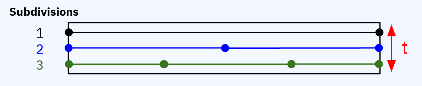
The block evaluates beam thickness t at each beam node. Linear beam elements have two thicknesses, and quadratic elements have three thicknesses. It also evaluates material properties at the element centroid; each element will have a single stiffness.
Tip:
For field-driven lattice thickness, higher beam subdivisions will give a more accurate representation of the lattice’s changing diameter and varying stiffness.
In the properties of the FE Lattice Mesh block under beams → properties, you will find information such as start points, endpoints, lengths, and line segments of the beam mesh in list form. You can drag these into the notebook for visualization or further use. Useful blocks for visualizing each index and working with these properties are:
List Element lets you bring in a list from your lattice beam properties and choose the index. If the list items are points or line segments, you can visualize these normally with the visibility toggle with the block selected. Changing the display color of the different points/line segments lists can also be helpful. If the list items are values, you can see the items with the chosen index at the top right corner of the block.
Sort lets you rearrange the order of your list items based on a chosen proxy. For example, sort the line segment list by its axis direction x property. The result would be a new list of line segments with indices ordered based on the x-axis.
FE Solid Mesh of Non-Lattice Surrounding Walls
Non-lattice geometry, such as the surrounding walls, can be meshed as a normal FE Volume Mesh and used as input for an FE Solid Component, then joined with the lattice component via a connector.
This combination of blocks converts your implicit body into a surface mesh, re-mesh it to be suitable for FEA, and then generates and discretizes a volumetric mesh with assigned nodes. If you have a CAD part, converting directly from it using the Mesh from CAD Body block is better to minimize tolerances.
Sharpen the geometry in the Mesh from Implicit Body block if needed. If the geometry is very simple, skip the Remesh Surface block.
The recommended tolerance for the Mesh from Implicit Body or Mesh from CAD Body block is 30% of the smallest feature in your part. Smaller element size or edge length in Remesh Surface and Volume Mesh is better here because there will be more nodes in proximity to the nodes of the lattice beams at the lattice-wall interface, which have to be joined together via a tie constraint.
Tip:
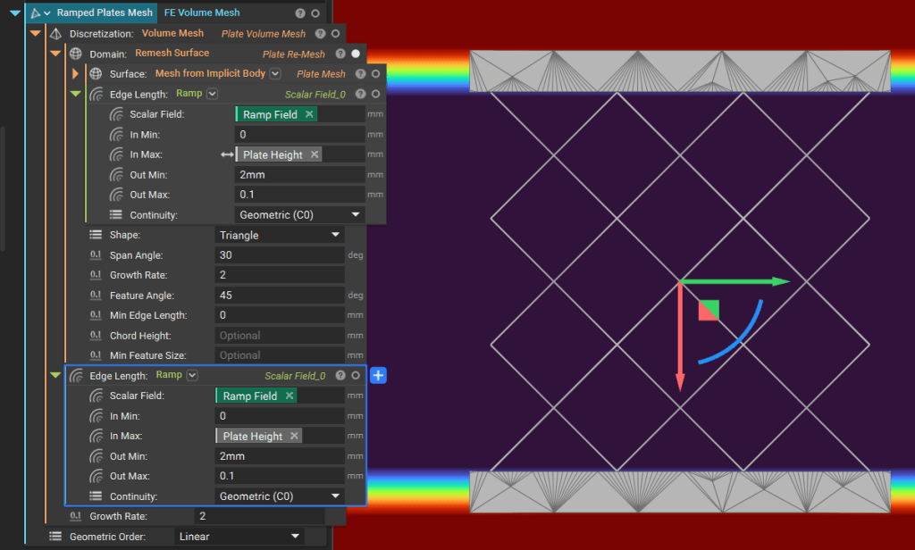
To increase accuracy, you can also use fields to drive your element size along the thickness of your wall so that they are the smallest at the interface with the lattice. This can be done by adding a Ramp block to the edge length input in Remesh Surface and Volume Mesh blocks.
Note that the two Ramp blocks you see are two instances of the same block, and changes in one are reflected in the other. You can also achieve this by making Ramp a variable and using it in both locations.
To see an example of how to apply this technique, see the completed file ‘Lattice FEA Using Beam or Shell Elements’, which is available for download at the end of this course section.
Components Connector
Use the Tie Constraint block to join the independent and dependent nodes of the solid and lattice components together.
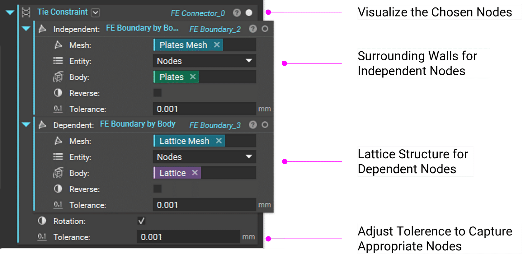
The right tolerance value to use depends on your geometry. Generally, the higher the tolerance, the more nodes you capture at the interface area.
Tip:
If your lattice beams are not well trimmed or there are upstream issues with the CAD part, increasing the tolerance can help you select desired nodes farther away from the interface area while sacrificing accuracy.