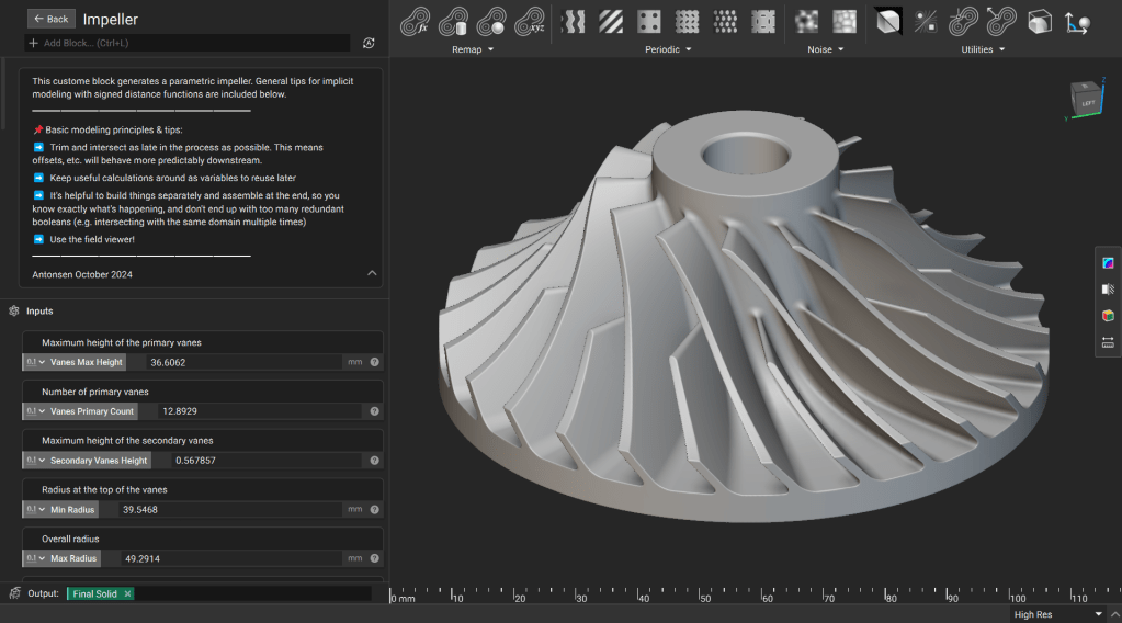
Parametric Impeller
This lesson demonstrates how to create a robust, parametric impeller using implicit modeling best practices. You will learn to use Signed Distance Functions (SDFs) to ensure your geometry remains stable across wide parameter variations while maintaining clean fields for downstream meshing and analysis.
Downloadable File:
This file was last updated in nTop 5.37.3
Modeling Principles
Keep these core principles in mind as you build the model:
- Trim and Intersect Late: Perform trimming and intersection operations at the end of your workflow to ensure offsets and blends behave predictably.
- Use Variables: Save useful calculations as variables to simplify your workflow and allow for easy reuse.
- Build Modularly: Build components separately and assemble them at the end. This avoids redundant operations and keeps your notebook organized.
- Field Viewer: Frequently use the Field Viewer (Hotkey: F) to inspect your distance fields and identify potential issues early. (How to use the Field Viewer)
Procedure
1. Generate the Central Body and Base Plate
Create the bottom plate and an “Untrimmed” (infinite) center cylinder. By using an infinite cylinder at this stage, you can apply large blends without distorting the final part.
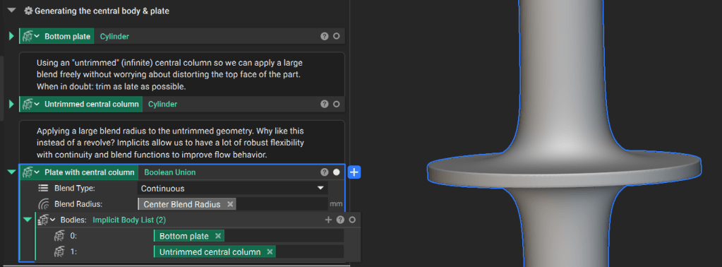
Tip: When in doubt, trim as late as possible.
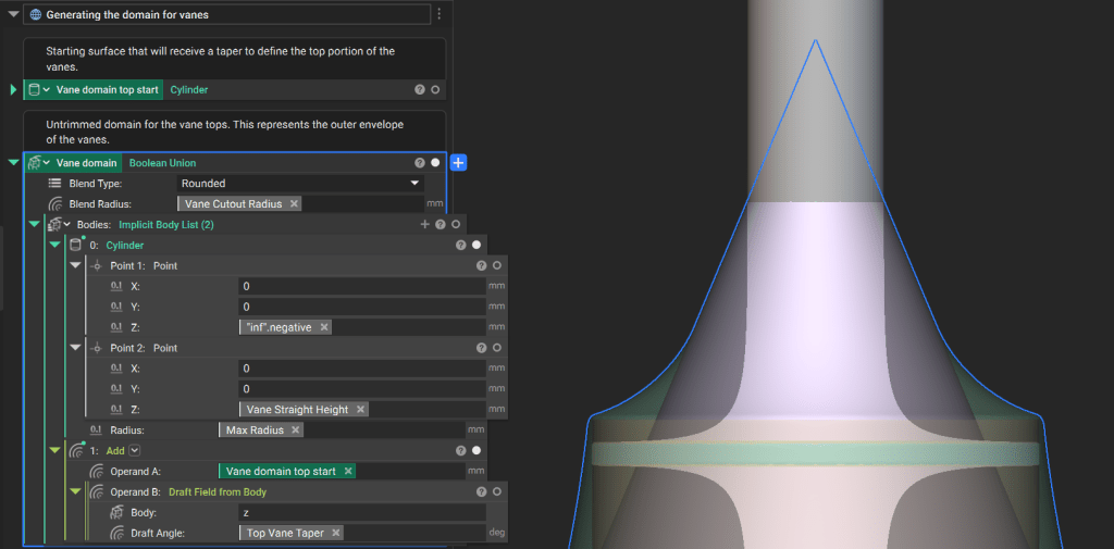
2. Generate the Vane Domain
Define the volume that contains the vanes.
- Create a drafted surface using the Top Vane Taper angle parameter.
- Use the Boolean Union block to combine this surface with a cylinder defined by the Vane Straight Height parameter.
- Apply the Vane Cutout Radius as your blend radius.
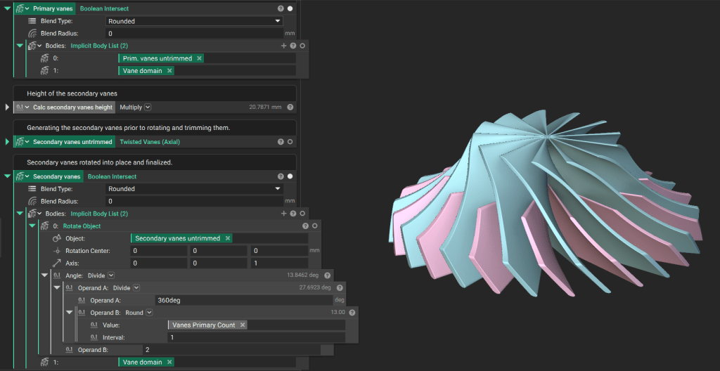
3. Generate the Vanes
The primary and secondary vanes are generated using the Twisted Vanes (Axial) custom block.
Downloadable File:
This file was last updated in nTop 5.37.3
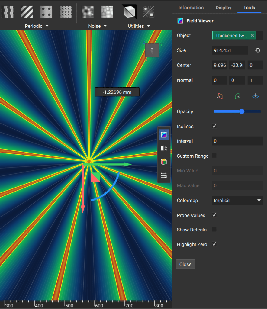
Field Generation: Create a polar array of infinitely thin fields. You can achieve this by taking the absolute value of a Plane starting at the origin. (Boolean intersecting the absolute value with the orthogonal plane ensures there is no forced symmetry.)
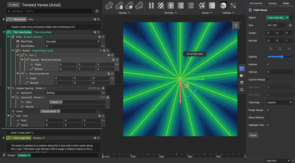
Tip: Use the field viewer! Learn more about using the field viewer in this support article.
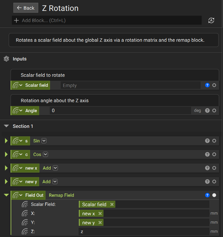
Twist and Thickness: Use a Z Rotation custom block to twist the vanes along the Z-axis using Remap blocks. Then, use the Thicken Body block to convert the infinitely thin fields into solid geometry.
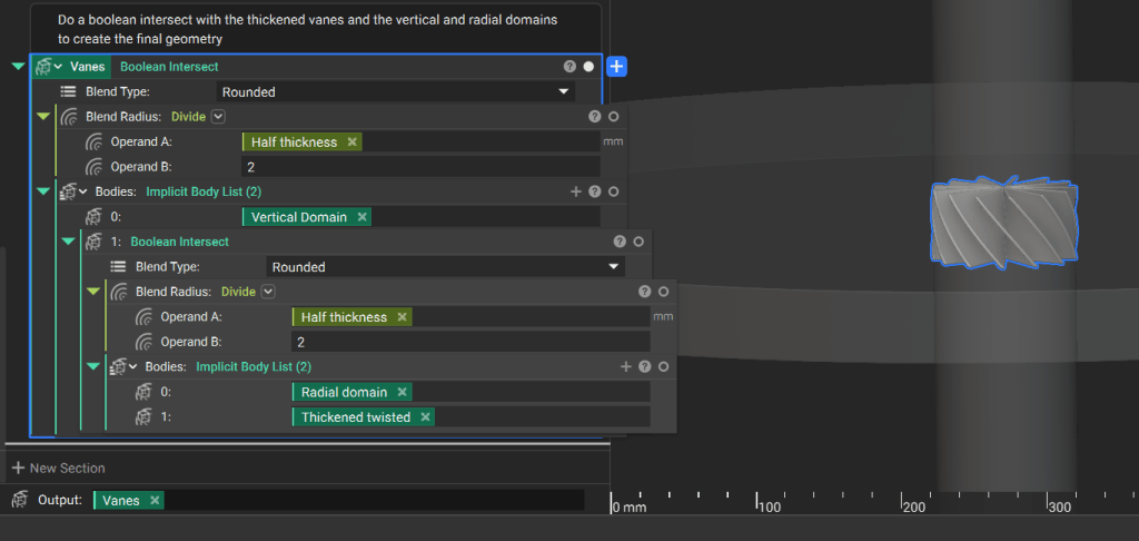
Use the Boolean Intersect block to trim the thickened, twisted body with cylinders that represent your vertical (based on height input) and radial domains (based on outer radius input).
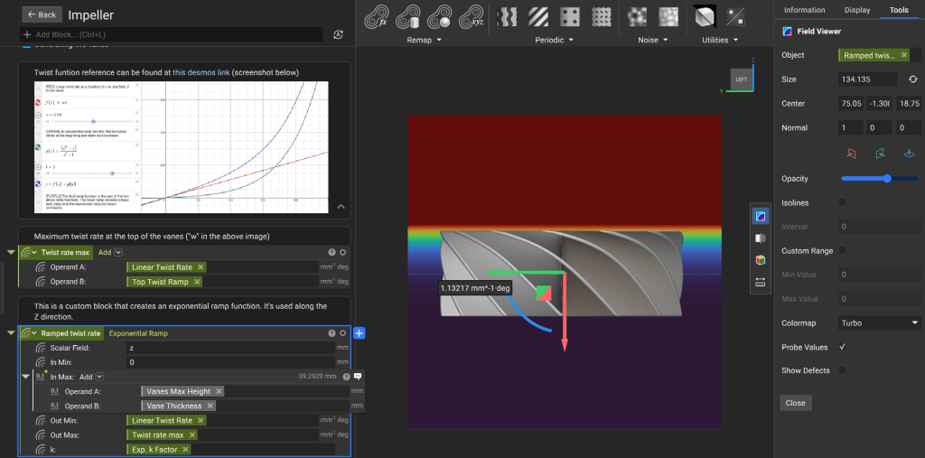
In the main notebook, define a “twist function” that varies exponentially along the Z-axis. The Exponential Ramp custom block provides precise control over the twist rate.
The Exponential Ramp custom block includes some mathematics that allows for more control over the twist rate than a typical Ramp block would (learn more about the Ramp block in this article: How do I use the Ramp Block).
Finally, perform a Boolean Intersect with the vanes that you generated and the “Vane Domain” that you created in the previous step. Rotate the secondary vanes by half the angle between each primary vane to position them correctly.
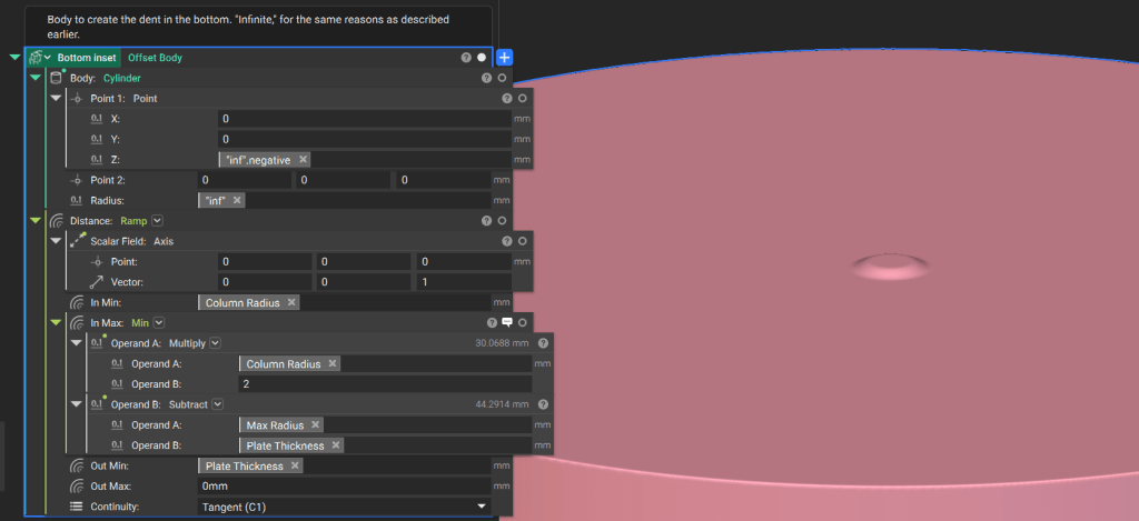
4. Assemble the Components
Underside Inset: Create an infinite cylinder and offset it using a Ramp function along the central axis. Use Tangent continuity in the Ramp block to ensure smooth transitions.
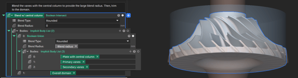
Use the Boolean Subtract block to remove the bottom inset from a cylinder, creating the overall impeller domain.
Join the vanes, central body, and base plate using a Boolean Union. Finally, perform a Boolean Intersect with the impeller domain to trim the entire body.
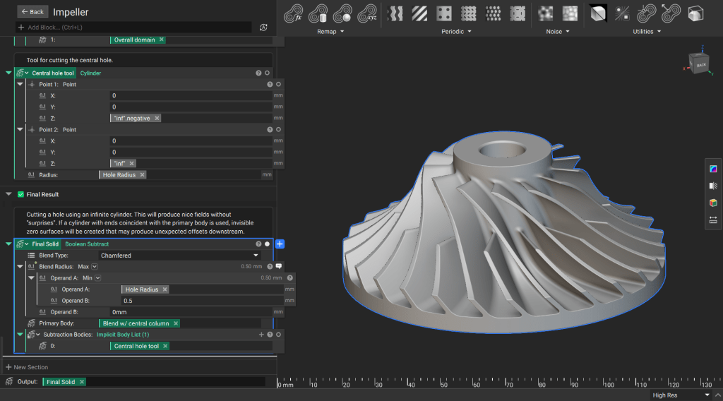
5. Final Result
Create an infinite cylinder for the center hole and use the Boolean Subtract block to remove it from the main body
Custom Block Conversion
To prepare this notebook for use as a Custom Block:
- Drag your Final Solid variable into the Output section at the bottom of the notebook.
- Move all relevant design parameters into the Inputs section at the top of the notebook.