FE Forces
Below, we discuss the different boundary condition options for a static analysis. You can find these forces in the Simulation tab under Boundary Conditions. We also have the Rotational Force block, which is currently in the Beta tab and is not discussed in this lesson. Information on our boundary conditions for thermal analysis is in our 341: Intro to Thermal FEA course.
To see the nTop notebook using all of these blocks in nTop, download the FE Forces file below this lesson.
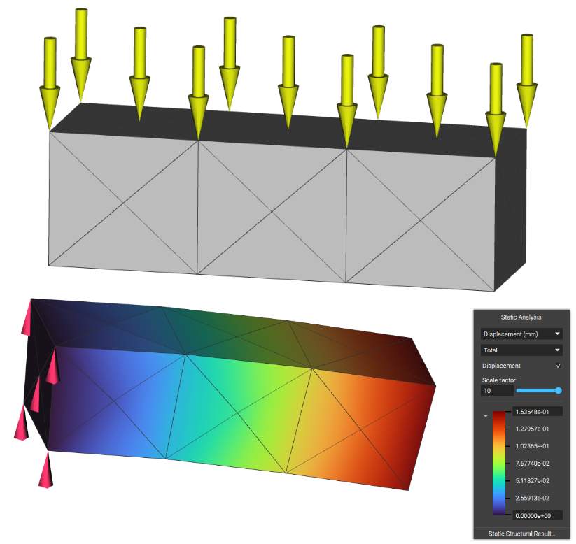
The Force block is a Boundary Condition for analysis that applies a force over a selected boundary. The force is evenly distributed over the selected entities. The Force block requires a Boundary to choose where to apply the force, and a Vector, to determine the magnitude and direction of the force. There is an optional input of a Frame, allowing for further definition of the orientation of the Force.
The downward arrows in the image represent the -1000N of Force acting in the negative Z-direction over the box. If you want more control over the direction of the force, you can edit it using the ‘Frame’ input.
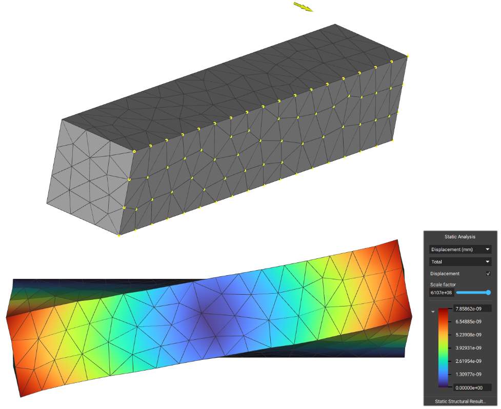
The Point Force block applies a point force to a selected boundary by distributing the load through rigid body elements.

The Edge Force block applies a force vector to selected boundary edge entities. The force will be distributed over the nodes on the selected edge. This block accepts a vector field for the force, so you can input a varying force across the selected edge entities, as shown below.

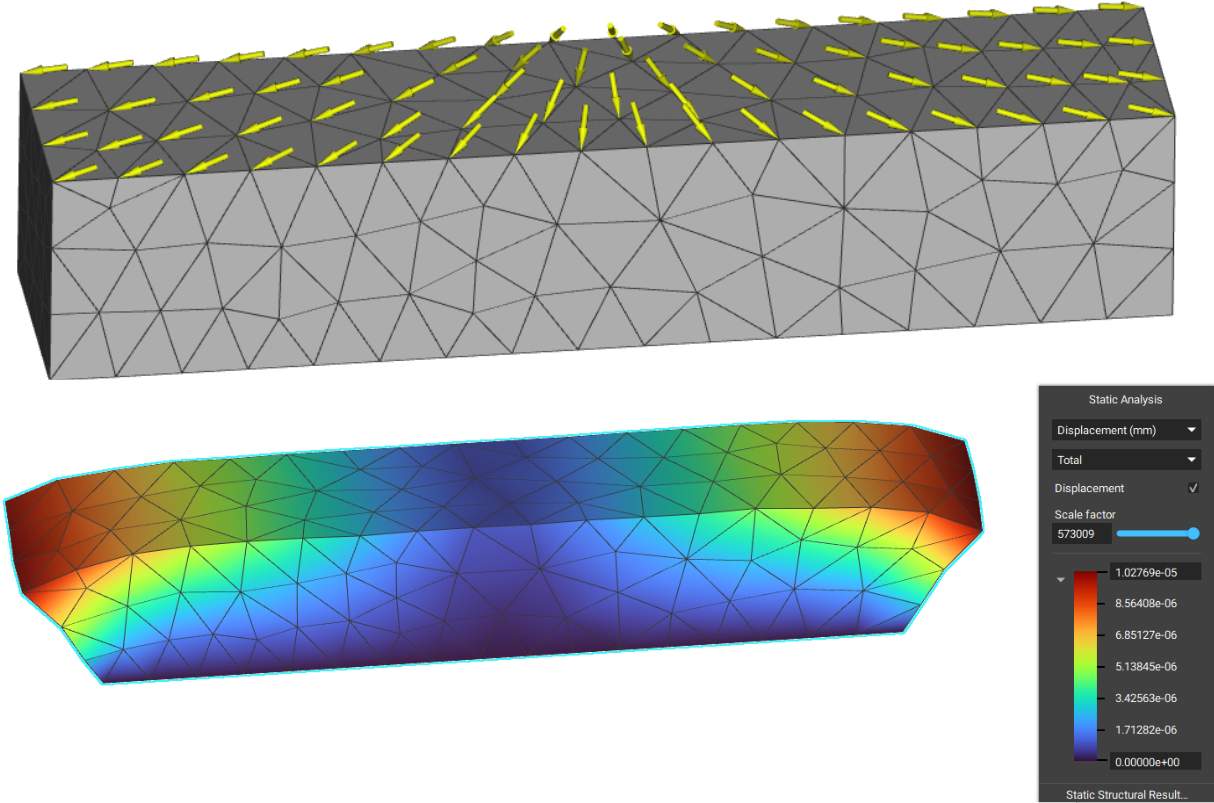
The Surface Force block applies a general force vector field to selected boundary face entities. The force will be distributed over the nodes of the selected faces. This block accepts a vector field for the force, so you can input a varying force across the selected face entities.
The Acceleration Load block applies an acceleration load to a selected region. The applied force is calculated by multiplying the acceleration vector by the element masses and distributing it over the nodes. You can use this block to add gravity as a load case.

The Point Moment block applies a point moment to a selected boundary by distributing the load through rigid body elements.
The Pressure block applies pressure to selected boundary face entities.
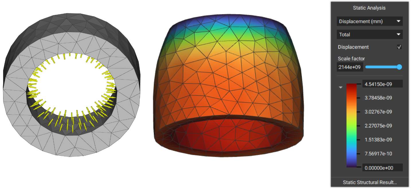
The Bearing Force block applies a bearing load on a cylindrical boundary based on a sinusoidal distribution.

Example File:
This file was last updated in nTop 4.2.3