Step-by-Step Guide to Parametrizing Motor Mounts
This step-by-step guide walks you through how to establish a parametric relationship between the wing geometry and the motor placement.
Start by opening the properties (click on the ?) of the “Wing Root Point” variable and drag the “x” property into the “x” value of the “Motor R Placement” block. Show and hide blocks with the radio button in the top right. “V” is the hot key to turn visibility on and off, “T” is the hot key to make a body transparent. This only captures part of the parametric relationship. Right click on the “Y” parameter for “Motor R Placement” and make a variable, then do some math to capture the effect of “LE Sweep Angle” on the motor placement.
To add a new block, start typing in an input field, double click between blocks, or search through the toolbar at the top.
This only captures part of the parametric relationship. Right click on the “Y” parameter for “Motor R Placement” and make a variable, then do some math to capture the effect of “LE Sweep Angle” on the motor placement.
To add a new block, start typing in an input field, double click between blocks, or search through the toolbar at the top.
 Do a similar process to capture the effects of the “Dihedral” angle parameter.
 This is not necessarily the best way to parametrize the motor placement – see if you can come up with a better approach!
Start by opening the properties (click on the ?) of the “Wing Root Point” variable and drag the “x” property into the “x” value of the “Motor R Placement” block. Show and hide blocks with the radio button in the top right. “V” is the hot key to turn visibility on and off, “T” is the hot key to make a body transparent.
This only captures part of the parametric relationship. Right click on the “Y” parameter for “Motor R Placement” and make a variable, then do some math to capture the effect of “LE Sweep Angle” on the motor placement.
To add a new block, start typing in an input field, double click between blocks, or search through the toolbar at the top.
Do a similar process to capture the effects of the “Dihedral” angle parameter.
This is not necessarily the best way to parametrize the motor placement – see if you can come up with a better approach!
Guide to Parametrizing Fuselage Splines
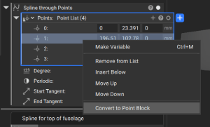
The top, side, and bottom fuselage curves are created with a spline that goes through a list of points. You can add additional points to the list by clicking on the “+”, and you can right click on points to re-order them in the list. Click on the radio button in the top right of the points list to see the points appear.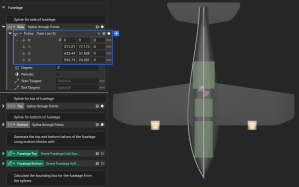
If you want to parametrize coordinates of a point, you can right click and select “convert to point block”. You can then define mathematic relationships between variables and specific point coordinates. In the screenshot below, I use the Y coordinate of the max point on the battery to drive the Y coordinate of a spline point.