Taking Shape
A heat exchanger’s shape depends on the application and available packaging space. If you’re starting with a clean sheet design, that’s undoubtedly the best-case scenario regarding design freedom. However, most nTop clients are trying to take traditionally designed and manufactured heat exchangers and convert them into ones that meet or beat performance requirements using additive manufacturing technology. Let’s say you are a fighter jet OEM. Over the past year of development, your customer has demanded higher computing capacity on the air vehicle due to software capability upgrades – this inherently introduces higher heat loads to the car that need to be managed. Often, a designer’s available packaging space does not change, which poses additional design constraints & challenges. No matter the scenario, nTop can help you find the shape with the optimum performance.
By leveraging the benefits of implicit modeling, we’ve learned a few best practices:
Developing the Outer Shell
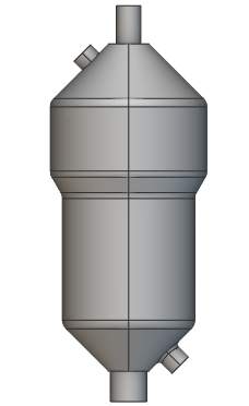
Have an idea of the print direction you want, so the outer shell can be designed to be self-supporting or have the minimum support required.
- For instance, the Outer Shell in the Image on the left would need a support base if the structure was printed in this orientation.
Standard HEX shapes such as pill/ovular volumes continue to prove highly effective when paired with nTop’s advanced lattice capabilities.
Once the design has been finalized, you can easily add variable thickness to the Outer Shell based on a stress field to further ensure compliance and remove unnecessary weight.
Developing the Heater Core Volume
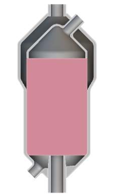
Generally speaking, the HEX Core Volume infills the entire Outer Shell. Therefore the contours and shape of the shell will dictate what the exterior portion of the core volume looks like and will influence how the flow behaves.
- See Image 1 below. While a simple shape the entire HEX Core follows the contour of the Outer Shell. In some cases, it might also be prudent to design from the inside out.
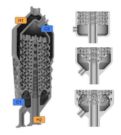
In other instances, the plenum region may also follow the contour of the Outer Shell, as seen in the top half of the image on the left or Section H1 in Image 2 below; these plenum regions don’t directly cut into the core but still may remove ‘working infill volume.’ Despite the removal of working volume, the plenum and transition regions into and out of the HEX Core is crucial to part success!
Other plenum regions will cut directly into the core, as seen in Images 1 & 2 below in Section C1. In all instances, it’s best if you can make the plenum cutouts within the HEX self-supporting to avoid entrapped support material

Utilizing CFD Fields in nTop (Advanced)
Typically we use CFD for final validation and verification. However, CFD at the onset of your design can reduce design cycle time and significantly impact your overall performance.
Two design considerations during Pre-nTop Prep are; generating the infill volume and the plenum/piping geometries into the HEX core.
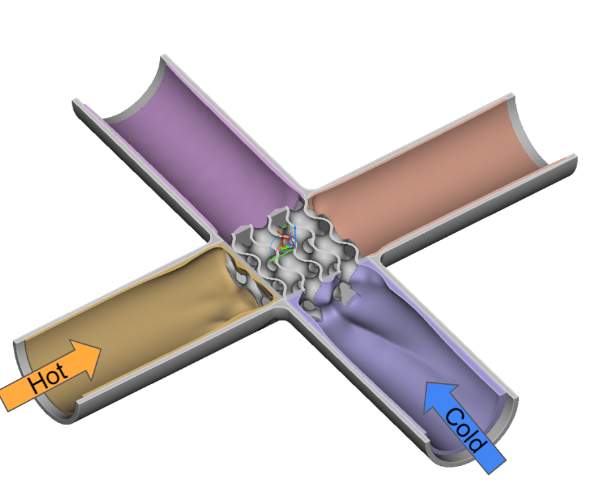
We can quickly generate these design considerations in nTop before any representational 3D geometry is built by bringing CFD results into the software. See GIF below.
To learn more, you can click on the video link Utilize CFD Fields for Flow Optimization or search ‘CFD data heat exchanger’ in our video library.

In the GIF above, an initial analysis is performed on the rectangular design space quickly seen as the start for both the hot and cold fluids. Both data sets are imported into nTop and a design space influenced by the flow dynamics is generated.