Standard Design Parameters in nTop
The ability to manipulate a given geometry virtually any way you can imagine is a very powerful tool when designing high-performance heat exchangers. nTop enables you to easily and quickly generate complex lattice structures and empowers you by exposing a suite of predefined and user-defined design parameters. In this section, it’s important to remember that as you manipulate/distort TPMS structure, you keep manufacturability in mind.
All the design parameters below will be influenced by performance requirements, the type of heat exchanger, and the fluid(s) used. For example, the operating temperatures and pressures of various fluids can significantly impact cell size.
Again, it is important to keep DfAM Considerations in mind when manipulating your TPMS lattice structure.
Probably the most fundamental parameter, but also one of the most important, regarding the surface area.
Our technology allows you to explore various cell sizes and quickly scale down or up in the total unit count.
Quantifies how quickly complex geometries can scale and how computational ‘expensive’ Implicit modeling is.

nTop allows you to discreetly fine-tune the length of your cell size in specific directions and or locations to control flow distribution & velocity, pressure drop, and other performance parameters.
Generally starts at a value of zero (0).
The bias ratio empowers you to discreetly tune the passage size/flow area on your hot and cold domains allowing you to fine-tune your pressure drop.
Inserting physical baffles into a flowing stream is a common technique to increase the path length/time a fluid takes through a heat exchanger core.
However, two common downsides to physical internal baffles are increased pressure drop and fouling rate.
Rather than inserting a physical baffle to redirect your flow, you could add a “virtual” baffle at the same location. For example, this “virtual” baffle can decrease the offset ratio locally to encourage the flow to take routes around that location. In this scenario, we are not entirely blocking off the flow area but simply reducing it so that flow can still move through. See Image 1 below.
A designer can easily utilize any incoming or native data source (CAD Body/ Points/ Lines/Test data/Simulation Data/etc.) to alter various design parameters to help achieve greater performance and meet design requirements. Once turned into an Implicit Field, We can use this data set to distort the shape of a lattice structure or surrounding components based on predefined criteria the designer or engineer chooses.
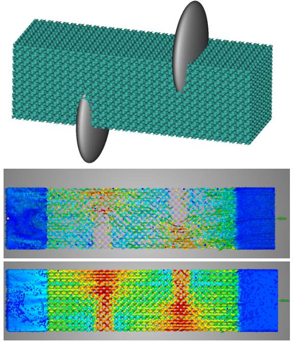
Image 1: In the first image above, the grey bodies are used to create virtual baffles which in turn constrict the flow in those regions, encouraging the fluid to move around them. The middle image is a velocity plot of particles moving through the HEX Core while the bottom has particles plus a color map of the total velocity through the structure. In the particle image, you can see how the fluid wants to naturally move around the constricted regions but is still allowed to flow through (bottom image).