Ramp Block
The Ramp block allows you to change a value based on a field. It can be applied to several types of scalar fields and allows you to rescale those existing fields to create new ones.

- Scalar Field: The field driving the Ramp. Define the In Min/In Max values based on this input.
- In Min/In Max: The values where the Ramp will begin (min) and end (max). These values are in relation to the Scalar field (with 0mm being the neutral edge of the field). Negative values go inside the Real Field, and positive values expand.
- Out Min/Out Max: The Ramp output values. Out Min is the output value at the In Min locations, and Out Max is the value reached at the In Max locations. They are the output field’s values as a function of the Scalar Field input.
- Continuity: Represents how the values will Ramp (by continuity order). See the image below to view the differences.
The values ramp between the In Min and In Max values. Before In Min, the value stays constant at the Out Min value, and after In Max, the value stays constant at the Out Max value.
Note: Include units when defining the Out Min/Out Max values.
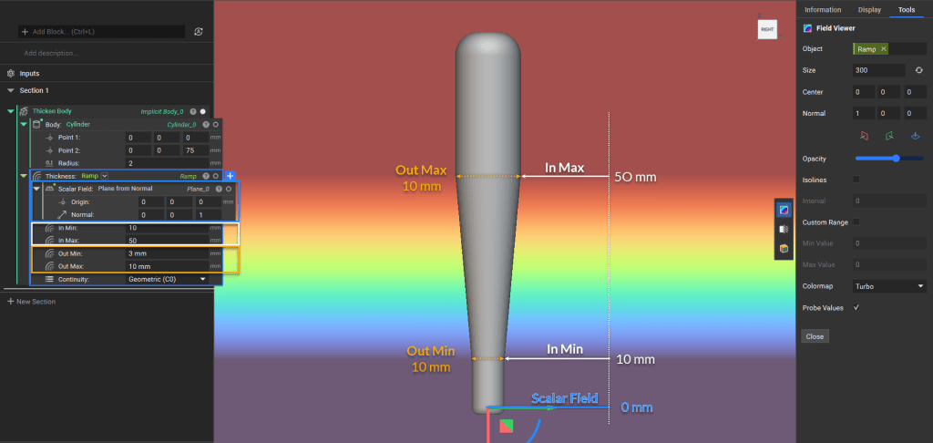
In this example, a plane was used for the Scalar Field input to create the gradual linear change seen between the start and end of the Ramp.
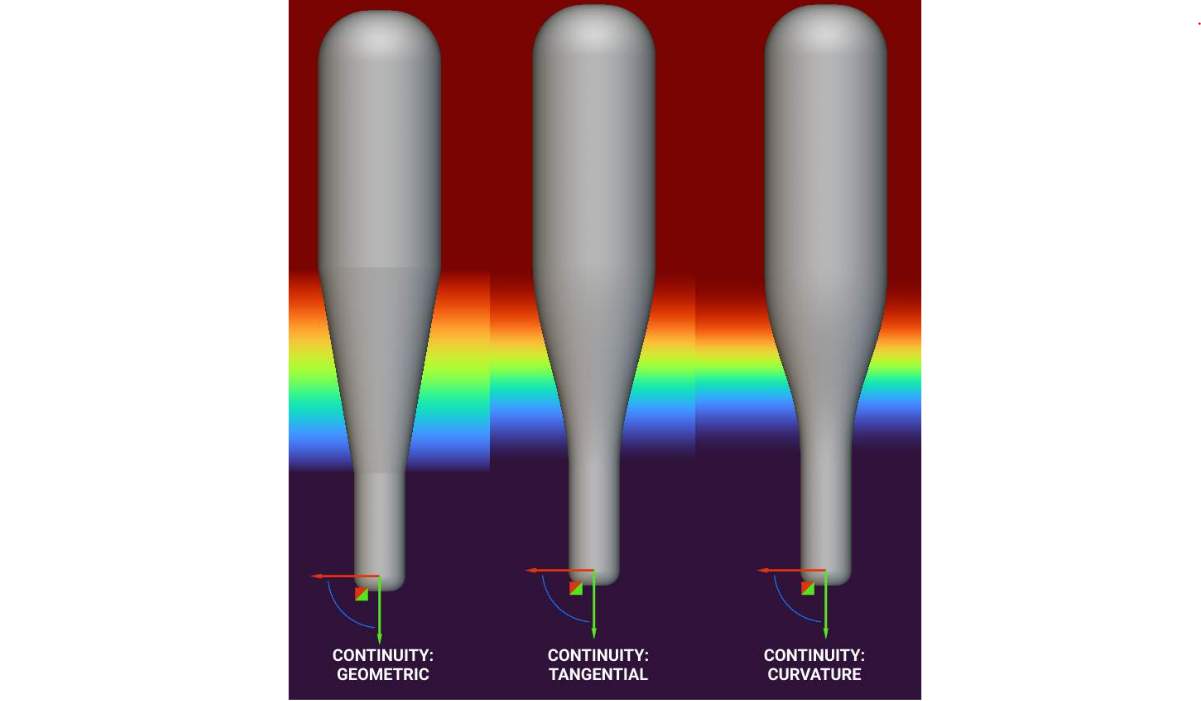
Visualization of the three different continuity options: Geometric (C0), Tangential (C1), and Curvature (C2)
The change does not always have to be linear, depending on the field used. For example, if you use the field of x2 to drive the Ramp block, you would get a quadratic change. See this article on the Help Center for a walkthrough on creating a quadratic Ramp.
Tip:
Use the Field Viewer to visualize the new field created by the Ramp block by selecting the block and using the hotkey ‘F‘. The new field will represent the output values assigned based on the spatial variation of the input field, which can then be used to control different design parameters.
Example Applications
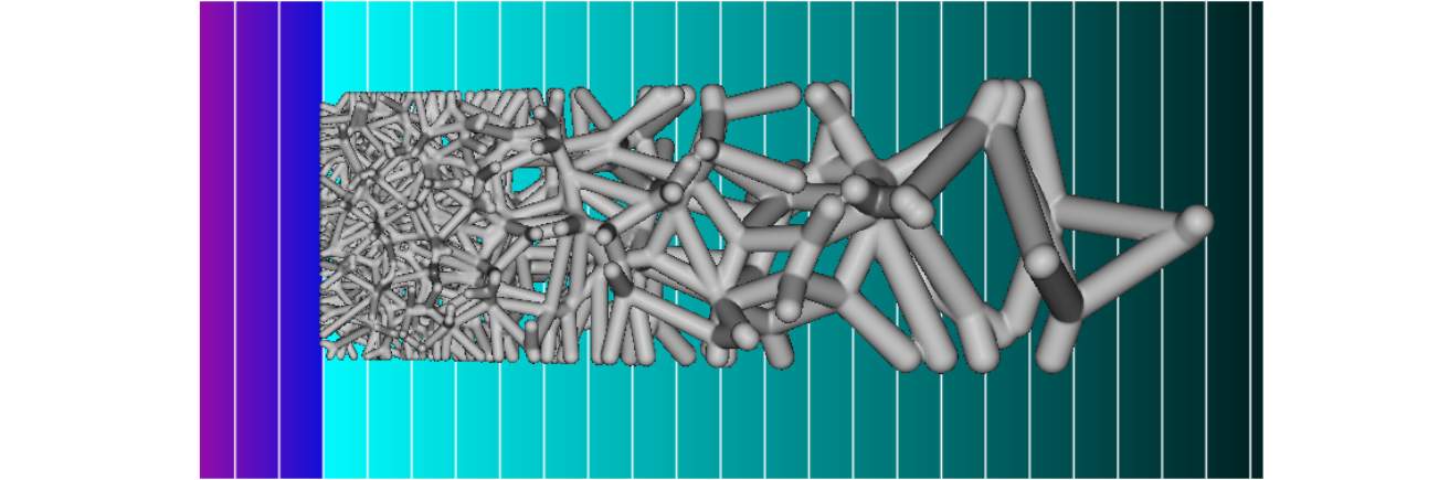
Manipulating density and beam thickness of a Voronoi lattice based on the field of a plane
This image shows the ramped lattice structure overlaid on the modifying field. The field modifies the seed point spacing and lattice thickness parameters.

Manipulating lattice beam thickness based on simulated stress data that has been converted into a field and smoothened
The lattice beams were assigned a larger thickness value at areas of higher stress and a smaller thickness value at areas of lower stress.