Field Viewer: Visualizing Fields in nTop
The Field Viewer is a tool for visualizing fields in nTop. It is a view option that lets us see a 2D section of a 3D field at a specified size and orientation.
To view a block’s field using the Field Viewer, press ‘F’ on the keyboard with the block selected or Right-click on the body and select Field Viewer here.
If the selected block outputs an implicit body, turn off its visibility to see the field’s negative domains.
Alternatively, you can access the Field Viewer from the View Tools on the right side of the screen or from the View tab in the Menu Bar. If no block is selected before opening up the Field Viewer, the Object input will be empty. Select the object to analyze by typing in the name of the block.
Note: While all implicit geometries have fields, not all fields render geometries that can be visualized using the visibility toggle. If a field does not have an enclosed negative domain that defines the inside of its body, the visibility toggle will not show any geometry or visual representation of that field. In such cases, the Field Viewer is the only way to visualize what the block generates. If you wish to visualize such a field, you can also use the Set Bounding Box to view the field in the input domain.
Position Settings

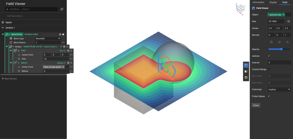
- Size of the Field Plane: The size of the field plane is automatically adjusted based on the selected object or the current view in the 3D scene, ensuring it is appropriately scaled for your visualization. If you want to reset the size of the plane, click the Reset Button next to the size input in the Tools panel to quickly set the plane to a size that fits the current viewport. You can also manually adjust the size of the plane by modifying the Size input in the panel.
- Position and Orientation of the Field Plane: When the Field Viewer is triggered by right-clicking on an object in the viewport, the field plane will automatically be centered on the selected object and oriented based on the surface normal. This provides a quick way to inspect the field data on the object’s surface. You can adjust the position or rotation of the plane manually if needed using the controls in the Tools panel and the gimbal in the 3D scene.
The Center and Normal can be adjusted by either:
- Manually typing in the values
- Dragging the gimbal by the straight arrow, arc arrow, or the two-colored squares
In addition to adjusting the size and location of the Field Viewer to cover the relevant area, you can adjust the Normal to view the field from different angles.
Warning: Depending on the orientation at which you are viewing your object, the field plane may not be visible. For example, if you are viewing an object on the xy-plane with the z-axis pointing in and out of the screen, then you would not be able to see the field if the normal of the plane is set in the x-direction [1,0,0] or y-direction [0,1,0].
Display Settings
- Transparency: By default, the Field Viewer will display the field with semi-transparency, so you can see the field data overlaid on your object while maintaining visibility of the underlying geometry. Use the Opacity Slider in the Tools panel to adjust the transparency level.
- Custom range: Option to adjust the minimum and maximum value
- Contours: Shows white lines of equal field values
- Colormap: The Field Viewer allows you to select different colormaps for better visual representation of the field data.
- Implicit Bodies: An Implicit colormap will be applied automatically when analyzing implicit bodies. This colormap is optimized to provide a clearer distinction of field values inside and outside the body.
- Scalar Fields: The default colormap for scalar fields is Turbo. However, you can select the Distance Field colormap or the Implicit colormap from the Colormap Dropdown to view the field with a different color scheme.
Tip: If you need to know the Max and Min values to understand the Colormap, the screen should show them as inputs when you toggle the Custom Range button.
- Probe values: Shows the value of the field at the location of the mouse cursor

