Different Ways to Create Fields
You will now learn about the different approaches for creating and defining fields in nTop that will enable an unmatched degree of design freedom. The following three lessons will introduce some important tools that use these fields as references to give you more control over any parameter in nTop that is represented by the scalar field symbol.

Extracting Distance Field of Implicit Bodies
Imported CAD or Mesh bodies do not have fields associated with them. However, once you convert them into implicit bodies, this generates distance fields. This means you can use any implicit body’s geometry to drive your designs.
You can use the implicit body itself as the scalar field input or go into the Properties panel and take out its Scalar Field chip if you want to manipulate this field further.

Using Equations
You can also manipulate and define fields with mathematical equations using the Scalar Field Variable block to create the x, y, or z variables. These represent the three axes and have fields that look like that of a plane set at the origin with the normal direction in the positive direction of the axis.

You can use mathematical operations such as multiplication and exponents with the x, y, and z fields, as well as math blocks from the Math tab, but it is important to be mindful of the units.

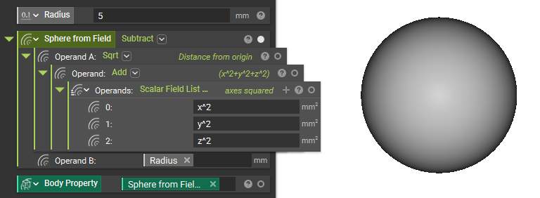
Just as you create fields from implicit bodies, you can also build implicit bodies from equations. However, to represent a geometry, it is best if the formula used is in implicit form for its signed distance function, which is often difficult to achieve for more complex shapes.
For a simple geometry like the sphere, the standard form equation is:

and the implicit form equation is:

The latter is the equation used to generate the field of a sphere. The resulting implicit body can be visualized with the visibility toggle and brought into the Notebook from the Properties panel.
But, in many cases, we are using a field to control variation, not to represent a solid object, so you are free to use any field we want — you don’t have to restrict yourself to signed distance functions.
Converting Data or Images Into Fields
Different types of data and even images can be brought into nTop, converted into fields, and then used to drive your designs.
Generating Fields from Data
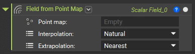
Any dataset can be imported in the form of point maps in CSV format using Import Scalar Point Map or Import Vector Point Map block, then interpolated using the Field from Point Map block to get values at other points to form a field.
There are four interpolation methods to choose from, including Natural, Linear, Nearest, and Barycentric. For extrapolation, the methods include Nearest, Linear, Exponential, and None.
Blocks for importing Point Maps

Block for converting a Point Map into a Field
Since we will use the resulting field to drive geometry, it may be a good idea to use the Smoothen Field block to create smoother transitions between values.

Note: The Smoothen Field block does not work on fields with infinite negative domains. This can be remedied by inputting a Bounding Box in the optional Domain input or by first using the Set Field Bounding Box on the field before inputting it into Smoothen Field.
The image below shows the comparison of each step of this process and the final field-driven geometry with variable shell thickness and gyroid-infill wall thickness.

The simulation and simulation result importation blocks directly generate relevant fields, which can be found in their Properties panels.
Tip:
If the simulation software you use does not support the native output file type, you can still import the results as a CSV point map.

Depending on the input point map, the overload of the Field from Point Map may switch to a non-field type. You can access their associated fields through the Properties panel in such cases.
Bitmapping Images
Bitmapping is a beta feature that takes an image and uses it to create a design. This can be applied to texturing or adding logo marks to a part.
Note: This Import Bitmap block currently only accepts PNG files.
You can import the image via the Import Bitmap block. To visualize it, use the Map Bitmap to Plane block. The imported file size is in the Properties of the import block. The Length and Width inputs of the Map Bitmap to Plane block adjust this size and can be used to either scale or warp the original image.
Blocks for importing and mapping Bitmap

Properties of the Map Bitmap to Plane block

In the Properties panel of the Map Bitmap to Plane block, you will find six color fields with values between 0 and 1. Each color has a different use case, depending on your application. For example, the grayscale color field would be appropriate if the imported file is a black-and-white image.
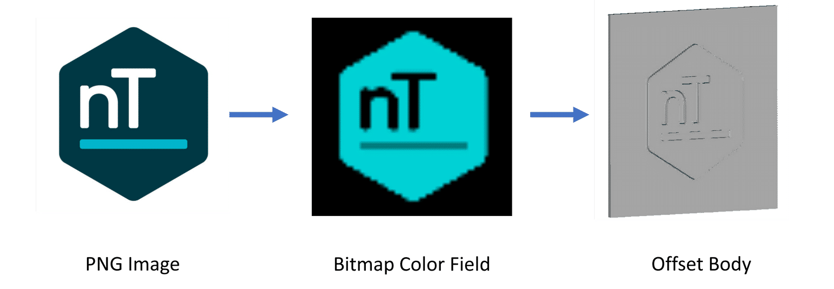
Bitmap color fields are typically used to drive the offset distance from an implicit body using the Offset Body block.